ASi bus system
ASi Bus Basics
The ASi bus system comprises four components: the ASi master, an ASi power supply, the yellow ASi cable and the ASi nodes.The ASi nodes are typically connected directly to the ASi cable using piercing technology and thus connected to the ASi master. This is a two-core, unshielded cable through which power as well as functional and safety signals are transmitted. It eliminates the need for complex parallel wiring.
The ASi master organizes the data traffic in the network and functions as a gateway to establish the connection between the ASi circuit and the higher-level control. It is treated like a fieldbus node by the higher-level fieldbus. This means that integrating an ASi network into an existing fieldbus or Ethernet system is just as easy as integrating any I/O module.
ASi Safety at Work
Thanks to the Safety at Work concept, it has been possible to seamlessly integrate safety-related components, such as safe sensors and actuators as well as safety monitors, into almost all popular automation systems. The advantage of ASi Safety at Work when compared to conventional safety solutions is that it enables the transmission of safe and unsafe signals on the same line. The previously required double infrastructure is now just as superfluous as all the costs associated with complicated separate wiring.
ASi Safety at Work is approved for applications that must meet safety requirements up to SIL3 in accordance with EN 61508 or PLe in accordance with EN ISO 13 849-1:2006.
ASi-5 – The New Standard
As of 2019, ASi-5 is the latest innovation stage of the ASi bus system – the globally standardized fieldbus system for the first level of automation. ASi connects sensors and actuators to a control system via a single two-core profile cable. The yellow ASi cable transmits power and data at the same time.
ASi-5 now enables you to transmit larger data volumes significantly faster. Thanks to a large data size and short cycle times – comparable to those of Ethernet systems – the AS-Interface can handle much more than it was previously possible. For example, ASi-5 now transmits analog values much faster and it is easier than ever to integrate smart sensors, e.g., IO-Link sensors with up to 32 bytes.
ASi Bus Protocol
The ASi master communicates with the other nodes in the ASi network. In an ASi-3 network, the telegram consists of 4-bit user data. In an ASi-5 network, there are typically 16 bits available for cyclic transmission – but profiles also exist with up to 32 bytes per node. Communication takes place using a serial transmission protocol for standard data. In the case of safety-related data, this is transmitted via a dynamized secure protocol. The AS-Interface telegram is absolutely interference-free. The data is always transmitted reliably even in harsh environments.
ASi Bus Topology
Thanks to the ASi cable and the piercing technology, the ASi bus system makes it easy to create junctions at any point in the system. The ASi Bus topology is freely selectable, e.g. ring, star or line structure.
Fields of Application
The open ASi bus system is suitable for use in all four areas of industrial automation technology:
Factory Automation

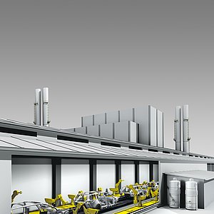
This includes automation solutions for areas, such as conveyor applications, packaging technology, machine tools and robots. In this respect, AS-Interface offers short response times, high reliability and the possibility to integrate safety technology on the same cable.
Process Automation
This includes automation solutions for areas in the food manufacturing industry, beverage industry, pharmaceutical industry, chemical industry, etc. The advantage of AS-Interface is that mainly analog/digital data is processed, and ASi meets the requirements for a stable and reliable standard really well.
Building Automation
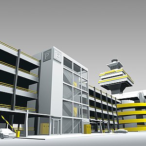
This includes automation solutions for areas in the heating, air conditioning, ventilation, fire prevention sectors, etc. Since simple installation and cable routing are just as important in building automation as the integration of functional safety, ASi is particularly well suited in these areas.
The Components in an AS-Interface Network
An ASi network consists of four components: the ASi master, the ASi nodes, an ASi power supply and the yellow ASi cable:
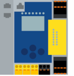
ASi Bus Master
The AS-Interface master connects sensors and actuators to the higher-level control via the ASi nodes. The ASi master can be used to forward digital and analog data, which has been read in decentrally via ASi nodes, to the higher level control through the respective bus system, and to transmit output signals from the control system to the actuators.
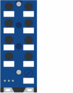
ASi Bus Nodes
ASi nodes are the communication partners of the master. Their task is to exchange their input and output data with the master – and to do so at the appropriate point within the data traffic. For this purpose, each node is assigned a unique address through which communication with the master is organized. Typically, 62 nodes can be connected to one circuit, depending on the ASi generation. The data that can be transferred and thus the areas of application differ according to the ASi generation: Whereas ASi-3 nodes allow up to 4 inputs and 4 outputs per node, where profiles are available for digital I/Os and profiles for analog I/Os, ASi-5 nodes allow up to 32 bytes of I/O data per node.
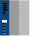
ASi Bus Power Supply
In conventional design, a separate ASi power supply (with integrated decoupling coils) is required for the voltage supply of each ASi circuit. With ASi Gateways and safety monitors of the version "1 Power Supply, 1 Gateway for 2 ASi circuits, inexpensive power supplies" by Bihl+Wiedemann, the decoupling coils are already built into the devices. This enables the supply of two ASi circuits by means of one cost-effective standard 30 V power supply together with a double master gateway or two single master gateways. With short cable lengths, even a standard 24V power supply can be used. This is an optimal solution for small and very small systems – i.e., for small machines with just a few nodes and a maximum cable length of 50 meters.
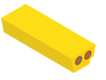
ASi Bus Cable
The ASi cable is an unshielded, 2-core cable. It not only transmits data and power, but also enables easy and cost-effective installation of ASi or ASi-5. Thanks to piercing technology, nodes can easily be installed on the profiled (thus reverse polarity protected) ASi cable – with perfect contacting and achieving protection class IP67. An additional 24 V supply is possible without any problems thanks to an additional AUX profile cable. .
ASi bus addressing
ASi Bus addressing is performed either directly via the master, an ASi Bus adress programming device, or via the commissioning wizard integrated in the Bihl+Wiedemann Software Suites.
Simple Addressing Using the Commissioning Wizard
Our intuitive commissioning wizard offers the easiest way of addressing. It can be used to identify, address and parameterize all hardware components on the ASi bus. As part of the Bihl+Wiedemann Software Suites (BW2916), the Commissioning Wizard is suitable for configuring and addressing all devices automatically, and guides the user step by step through the addressing process.
ASi-5/ASi-3 Address Programming Device
The modern ASi-5/ASi-3 Address Programming Device (BW4708) is a compact device for addressing all ASi-3 and ASi-5 modules – with a uniform workflow. It has an OLED color display, a port for the ASi-5/ASi-3 addressing cable and a USB-C port for easy connection to the PC. It also enables seamless integration into the Bihl+Wiedemann Software Suite.
ASi Error Detection
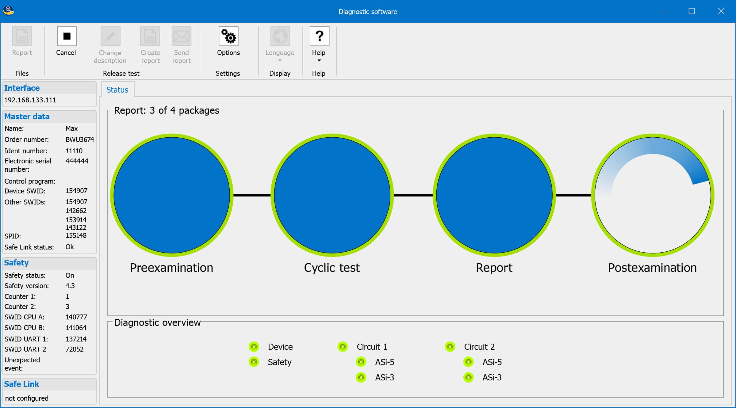
Faults in ASi networks can be identified and corrected quickly and easily using special diagnostic software. The software is mainly used for commissioning and maintenance intervals and provides both specific and detailed information on errors that have occurred and concrete recommendations for solutions. If an error occurs, it is clearly displayed in the software screen. Therefore, even inexperienced ASi users receive direct "assistance for self-help".
The ring buffer facilitates troubleshooting and enables continuous measurements for up to 24 hours over a period of up to one week.
Video Tutorials
You can find even more helpful information and tips in our tutorials. They make it easier for you to work with the Bihl+Wiedemann software. Many video tutorials also include a quick start guide as PDF.
To watch the video tutorial, you need to register or log in register or log in.

